
The process of production illustrated below of a Roland Iten SUPERDRIVER mechanical buckle is taken from Roland’s new manufacturing partner, Montanari S.A., based in Saint-Imier in Switzerland’s Jura Mountains. All components for the buckle are made by Montanari, only a handful are shown here.
In 2019, Roland Iten brand merged its prototyping and small-series manufacturing workshop with Montanari S.A., who in turn became the brand’s exclusive production partner.
A finished Roland Iten SUPERDRIVER buckle made by Montanari.

The buckle has two settings that allow the tension of the belt once attached to the buckle and being worn by the user, to be easily adjusted through a lever system. In addition, the mechanism by which the belt is fixed to the buckle allows for a quick release system to alternate between different material and colour straps.
Below, examples of the CAD (Computer Aided Design) that follow the design process, upon which the components are machined

The section of the buckle that will hold the tail end of the strap, unfinished.

The main chassis of the buckle finished and decorated.
The CAD process allows for the buckle to be virtually assembled and tested. Colours can be altered from an aesthetic perspective as well as decoration, engraving and surface finish. Once completed the files are transferred and converted to be used for the manufacturing process of each part.
There are many different techniques available to be used in the manufacturing of any single component. Part of the process of production is the choice of which manufacturing technique to use. The choice is influenced by size of the part to be made, material, quantity, precision and cost.

The machine drawings for production of the ‘driver’ and the main chassis inside a rectangular titanium plate.
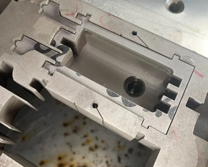
The chassis shown still sitting in the thick titanium plate.
The first process in making the chassis and driver as well as multiple other components is cutting out the basic form, using wire (also known as spark) erosion. This allows the complex outer forms to be machined.

When machining, multiple components can be made from a single plate. Here the chassis and the driver are cut from the same plate. The driver (sitting on top) is a finished piece.

An example of a finished chassis.

The block sitting around the driver (center piece) is waste material that will be recycled. This material lies between the driver and the chassis. The circular hole is the access point for the wire that cuts the profile of the piece. Once the form is cut the wire moves on to cut the next piece, its exit route can be seen below the center of the block.
Machining the leverage clip that hold the tail of the strap in place in the buckle.

The wire erosion machine.
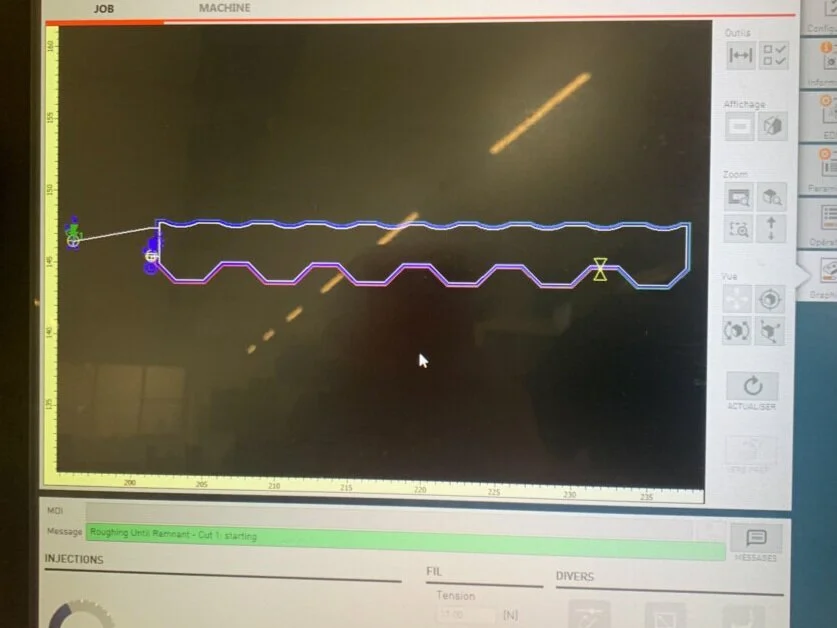
Close up of the screen with the route shown that creates the form of the pieces.

The pieces being cut from the titanium plate.

Recto

Verso
Once the above section is made the piece is then cut again and machined into two pieces, then decorated until the below sections are formed.

The central rib that holds in place the driver section of the belt.


The before and after of the rib, the piece is brush finished before being lazer engraved.
Parts of the release mechanism of the strap.

The square axel that traverses the width of the buckle.

The unfinished side section of the release system of the buckle

The two pieces assembled in their unfinished form straight forms direct from the machine.
The side levers of the assembly.

The next process following the wire erosion is milling the different levels in the pieces and drilling the holes.

The milling machine used to cut the different levels as well as produce the relevants slots in the piece.

The cutter used to machine the slots in the side of the piece.

Fixed to the lower plate is the un-slotted piece, sitting above it is the slotted piece.

The finished, unassembled pieces.
Decorating the release-roller assembly.

The flat sides are straight grained on an abrasive paper.

The curved surfaces are polished.

The finished and assembled pieces.
The titanium chassis being brush grained decorated.

Different grains of abrasive material are used when removing machining marks through to the final surface finish.
Sand blasting a plate to remove the machining marks and any burs present after machining, prior to it being decorated.

The sandblasting machine. The sand is blown through the central pipe.

The operator places his hands through the side sections, holding the piece to be sandblasted to keep the sand within the machine.

The left hand piece after sandblasting, the piece to the right with the machining marks as it leaves the machine.
The lazor engraving

Once the design of the engraving is decided in relation to aesthetics and size, the piece to be engraved is placed into the machine, blocked in a brace system to prevent it from moving. Before the piece is etched, the surface is coloured using ink and a test is made to assure position and design. Once this is validated by the operator, the etching is launched.

The lazor etching machine.

The piece in position for the test.

The piece after etching.
The surface resulting from the etching is dark and mat in finish. Once the upper surface has been straight grained the result generated is a clear contrast between the two surfaces.
A selection of the pieces made from the wire erosion process.


A selection of the finished components the buckle comprises of. All screws are absent from image.
The final buckle.

Images from the Montanari workshop.

Upright drilling machines.

Manually operated milling machines.

CNC machines.

Various lathes.
Montanari S.A. manufactures precision mechanical parts primarily for the machine and watchmaking industry, as well as for the medical sector and aeronautics.
Montanari S.A. is part of a larger group called Groupe Froidevaux that has two other entities: Froidevaux S.A., a specialist in the fabrication of plates for pad printing, and FCDH Aciers S.A. a company active in the sale and development of fine steels, in metallurgical consulting and training.
To learn more about Montanari
To learn more about Roland Iten